Why didn't Acorn put a TAB key on the Electron? And why was the <SHIFT LOCK> key left off too? It's not as if there wasn't enough room to accommodate these useful keys either mechanically or electronically.
To rectify this oversight, I have designed a couple of circuits. The first simulates the TAB key by using the <CTRL> <I> key sequence and the other toggles the <SHIFT LOCK> "on" and "off".
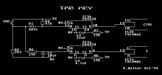
TAB
- Press <CTRL>
- Press I
- Release I
- Release <CTRL>
This translates into the electrical waveform:
                ______________________________
         ______:                              :____________  CTRL

               :<-----------"t1"------------->:
                              ____________
         ____________________:            :________________     I

               :<---"d1"---->:<---"t2"--->:
The circuit had to produce two outputs, CTRL & I, whose waveforms have the above relationship. I have included diagrams showing the circuits which can be accessed from the Articles Menu.
In Operation
Pressing and releasing S2 triggers IC3b (a retriggerable monostable) immediately which in turn switched on IC2b (a bi-lateral switch). This effectively closes the CTRL keyswitch for 300mS (t1).
When IC3b is triggered, R6/C2 delays the trigger of IC3a for 150mS (d1). After the 150mS delay IC2a switches on, effectively closing the I keyswitch for 75mS (t2). R6/C2 also debounces the S2.
IC2a pins 10 & 11 are wired to the "CTRL" keyswitch and IC2b pins 1 & 2 are wired to the I keyswitch on the keyboard.
<SHIFT LOCK>
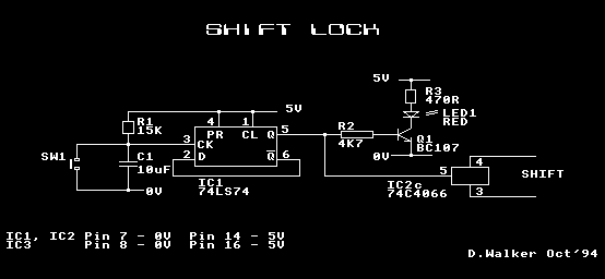
IC2c pins 3 & 4 are wired to the SHIFT key on the keyboard.
Construction
The construction of the circuit was done on Vero board but a circuit board could quite easily be designed and produced. The boards mounting will depend on your system. I mounted the circuit on the left hand side of the keyboard next to the <SHIFT> and <CTRL> keys - this space is only available to those who have moved their Electron circuit board into a Slogger RX case or similar box. It could be mounted somewhere behind the function keys or alternatively in a separate box.
Parts List
| R1 | 15K | 0.25W | C1 | 10uF | 16V | IC1 | 74LS74 |
| R2 | 4K7 | 0.25W | C2 | 10uF | 16V | IC2 | CD4538 |
| R3 | 470R | 0.25W | C3 | 22uF | 16V | IC3 | 74C4066 |
| R4 | 47K | 0.25W | C4 | 4.7uF | 16V | ||
| R5 | 2K2 | 0.25W | |||||
| R6 | 15K | 0.25W | Q1 | BC107 | SW1,2 | Keyswitch | |
| R7 | 15K | 0.25W | D1 | OA91 | |||
| R8 | 15K | 0.25W | LED1 | RED | |||
Derek Walker, EUG #17